Sunday, March 24, 2019

JANUARY 21, 2019

"AHHhh... Houston... We've got a Problem..."
NE Vertical Submerged in Frozen Salt Water
Dayem! Yesterday's storm surge, combined with the Blood Moon abnormally high tide this morning, swamped Succotash Salt Marsh at 7 AM, submerging the Northeast vertical underwater. Actually, ice. I knew it would happen by monitoring the local tide charts, and attempted to raise the NE vertical yesterday when temperatures were a balmy 28˚. 

"Huston, We've Got a Problem"
Storm surge swamps vertical.
Dropping temperatures freeze salt water into ice.

***

Here's the system impedance and reactance of a pair of submerged saltwater verticals to the Northeast, Southwest and broadside, as measured in the shack this morning. 


Feedpoint Impedance and Reactance of Submerged Phased Verticals
Northeast, Southwest and Broadside
***
I am waiting for the tide to drop so I can go out there in 0˚ temperature to attempt to raise the Northeast vertical by several inches. I think I can do this by unguying it and raising the aluminum tube up in the PVC insulator tube, drilling a new hole to set the bottom retaining screw at a new height. Not a problem given the design of the vertical base support scheme. I tried to do it yesterday afternoon, but lost light while raising the more-important remote switching relay box higher above the high tide waterline. She survived without getting swamped. (Editor: actually, this was not the case. As we shall shortly see, the problem was in the switchbox which had been repeatedly subjected to immersion in salt water at previoous high tides). The only problem with doing this is that it is extremely cold outside, and the waders aren't insulated. This morning the air temperature was so cold that The Marsh and Atlantic ocean were steaming like a hot cup of coffee. I shot photos and video which I will edit and post on YouTube later this morning. 
 
Point Judith, Rhode Island
Cold air temperatures caused sea water to steam like hot coffee.
***
I have installed the L-match into a tackle box in order to mount it in The Marsh next to the remote switching relay. This will enable me to establish a 1:1 SWR and zero reactance down the feedline heading back to the shack, as well as install a dozen ferrite beads between the switchbox and the L-match. This might quiet-down even further the common-mode noise on the coaxial feedline heading back to the shack. 

L-Match Readied for External Installation
A tacklebox serves as weather-proof enclosure for the L-Match.
Matches 38-Ohm impedance tio 50 Ohms.
***


JANUARY 14, 2019

Site Survey
Here's what we got so far. 

A Shack with a View
Phased verticals always in view from the operating position.
***
Asia, Longpath
Salt marsh extends to seaside homes situated on the Atlantic coast. 
***


Ground Systems: Southwest and Northeast Verticals
Hopefully dispelling the notion that the ground system is not important. 
Ground rods connect through green wires. Ground radials attach to ring. 
Rf choke bleeds static electricity build-up.
***

JANUARY 13, 2019

2nd Bleed Choke Installed
Installed the second RF choke across feedpoint of Northeast vertical. Both verticals now are so equipped.

Homemade vs. Commercial: Static Bleed Chokes
To the left we see the 2nd homemade choke installed today on the Northeast vertical. Cost: $0. 
On the right we see one sold by Array Solutions. Cost: $40.

JANUARY 10, 2019

Checking the F/B on 7.220 Mhz
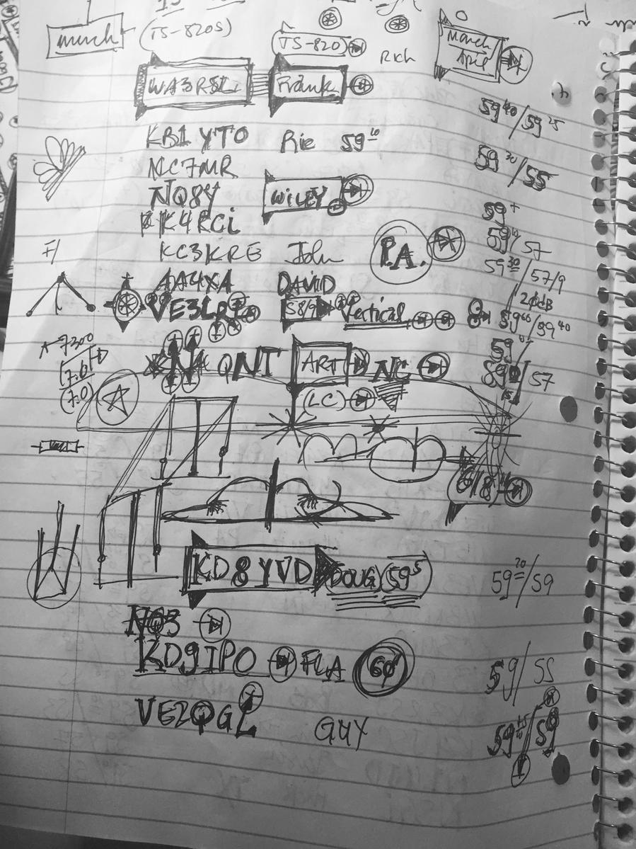
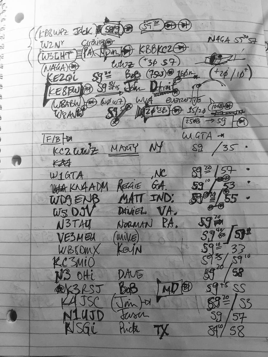
Tonight we ran F/B checks on 7220 Mhz during which about 50 amateurs, who presumably follow events posted on this QRZ.com page, provided F/B reports. In addition, and quite to my delight, several hams who could not wait through my slow pile-up operating style opted to email me in their F/B impressions! Thank you, guys! Below we see the operating position at the height of taking F/B reception reports, as well as the desk notes this session produced during its three-hour duration.

QRZ.com Readers Submit F/B Reception Reports
In Massive 3-Hour Pile-Up on 7.220 Mhz.
***

I added the 6" segment of coax to the phasing line to "walk" its maximum F/B down from about 7280. However, and as detailed in previous updates, this locked the phased verticals into one another producing prodigious F/B over a wide swath of frequencies, from the CW portion of the 40 Meter band all the way up above 7.2 Mhz. Thus I selected 7.220 Mhz to check the F/B to see how the verticals were performing so far above the design frequency of 7.1 Mhz. The results were fascinating, the highlight perhaps being Canadian maritime stations reporting the exact opposite results from those submitted from amateurs situated to the Southwest. Of course, this is what is supposed to happen, according to theory. But it is always exhilerating to see theory confirmed empirically. After the F/B ratio reports were written down in the "scientific notebook" maintained in the shack, I looked up each station on QRZ.com and recorded their azimuth bearings in for inclusion in the table submitted below for your hopefully enjoyable review. Thanks everybody!

F/B Table
What we're looking for is the following. Since the phased verticals are sited 60˚ Northeast and 240˚ Southwest, we compare the F/B reports to their compass bearings. The F/B ratio reports from stations situated on or near either of these two bearings, 60˚ and 240˚, are looking directly into the then away from the forward lobe. Their's will be front-to-back observatiuons. Reports received from stations situated 90˚ off these bearings, e.g. 150˚ and 330˚, will be situated perpendicular to the array's F/B pattern, and expected to see no difference at all. From these stations we should see smaller F/B ratio reports. Stations situated about 45˚ +/- the main lobe bearings (60˚, 240˚) might be seen providing the largest F/B reports since they will be seeing the forward lobe and then one of the array's rear-quarter nulls produced to create the small nub off the rear-end due to non-optimum tuning of the F/B. Hence we look to see if stations +/- 45˚ (or so) off-axis from the dead rear-end reporting higher F/B ratios. All of this is, of course, quite subjective. But it is fun to do, and represents the way original spark gap poineers shared with others, through wireless means, the results of their individual tinkerings with the ether. And that is exactly what we are doing here. 

JANUARY 10, 2019

The Thrill of Empirical Confirmation
 
All I can say is BiNgO! After the installation of the 7" piece of coax, the F/B has not only been walked down to 7.1 Mhz, but is presaent throughout the 40 Meter band! I never thought that would be within the realm of the possible. But all indications on receive indicate a significant expansion of the F/B in absolute terms, as well as its manifestation across a wide sweep of frequencies: 7.0 Mhz to 7.3 Mhz. It's everywhere! I perform some random tests between 7.130 Mhz and 7.180 Mhz, and all reports surpass ones previously collected a day or so before when the extra 7" of coax were not in place. The next day I plan to conduct an extended F/B check on the air with amateurs who are following all of this on this QRZ.com page. 
 
After installing the 7" of coax into the phasing line, the numbers read by the MFJ analyzer at the remote switching relay box locked into textbook purfection. 37 Ohms+j7 for Northeast, 38 Ohms+j7 for Southwest and 41 Ohms+j17 for Broadside (Omni). Awesome! When I saw the numbers in the field, I knew something "was up". It was not until I got back into the shack and started flipping the verticals NE/SW that I realized the extent to which the entire system had locked-in to itself.

Perfect Readings: Northeast, Southwest & Broadside (Omni)
Measured at the remote relay switch box after lengthening phasing line 7".
 
***


JANUARY 9, 2019

Fine-Tuning the Christman Phasing System

Now the Hard Part
Tuning the array is the last task. 
***
From flipping back and forth between NE and SW for a day or so, it has been determined that the F/B is maximized around 7.280 Mhz. Now that the NE vertical has radials and has been re-resonated, I will now walk the F/B curve down in frequency and park it where I want it, which is 7080 Mhz. This will afford excellent F/B in the CW and DX phone sub-bands between 7.2 Mhz and 7.0 Mhz. To do this I have to add a tiny bit of coax into the 71˚ phasing line out at the remote relay box. I am able to do this now because both verticals are exhibiting nearly-identical impedance and reactance sweeps. 

Methodology: Moving the F/B Ratio Curve Up and Down in Frequency by Adjusting the Christman Phasing Line Length
  • First we have to calculate how long 71-degrees of RG-8X is at two frequencies: where it is presently maximized and where we want it to be maximized.
  • Once we do that, we subtract the length of the shorter coax (71˚ @ 7.280 Mhz) from the longer coax (71˚ @ 7.080 Mhz) to see how much coax to add to the shorter piece to make it as long as the longer piece.
  • Then we cut a piece of coax that length and solder PL-259s on each end.
  • We then put on the waders, go out into the salt marsh and insert the little patch cable into the phasing line using a barrel connector. 
Calculating Christman 71˚ Phasing Lines
  • [300/frequency] x feet/meter x velocity factor of coax  = 1 wavelength of coax at frequency specified.
  • Since that length represents 360˚ of the frequency's sinewave, we multiuply this length by how much 71˚ is of 360˚. This is, of course, the fraction: 71/360. 
  • So we multiply the 1 WL coax by 71/360 to arrive at how long 71˚ of it is. 
The 7.280 Mhz and 7.080 Mhz calculations are provided below:

[(300 / 7.280) x 3.28 x 0.82 x (71/360)] = 21.859 Feet @ 7.280 Mhz

[(300 / 7.080) x 3.28 x 0.82 x (71/360)] = 22.476 Feet @ 7.080 Mhz

We now subtract the longer coax from the shorter coax to see how much coax to add to the shorter coax to make it as long as the longer coax. 
This will lower the frequency of the F/B ratio curve from 7.28 Mhz to 7.08 Mhz. Or so I think. Thus,
22.476 - 21.859 = 0.619 feet or 7.4"
So the next step is to prepare the little piece of RG-8X coax, and solder a couple PL-259s on the ends. 

Fine-Tuning the Christman Phasing Harness
7" of RG-8X
***
Believe it or not, this is all that is called for according to our observations switching the array back and forth for a day or so, as derived by our mathematical calculations. Seven (7) puny inches of coax inserted into the Christman phasing line out in the marsh. At times like this we think we might be crazy to think such a simple thing will walk the perceived F/B down 200 Khz to the design frwquency of 7.1 Mhz. But then we recall the original spark gap operators of a century ago, and the spirit they had for experimentation and for giving things a try based on their own observations. We put on the waders and head out to what several on the air inadvertantly refer to as "The Swamp". Let's see what happens after this simple adjustment. If anything, this constitutes one of the finer points of tuning phased verticals which, hopefully, others will perform. Remember, at this point we have received some fairly good F/B reports.


QRZ.com Readers Check-in via Email
Hank, K3YDX and Mike, VE3MEU
***


JANUARY 9, 2019

Phased Verticals: Re-Resonating NE Vertical • F/B Locks In

Re-resonated Northeast vertical this afternoon, dropping it from 7.5 Mhz to 7.15 Mhz -- requiring 1.5 feet lengthening. Added a RF choke to base of Southwest vertical to bleed static build-up from it.

Homemade Static Bleed Choke
AWG #16 enamel copper wire wrapped around 3/4" PVC tube • bleeds static off vertical
***
Upon return to the shack the following readings were taken at the feedline.

System Feedline Sweeps
Northeast, Southwest & Broadside (Omni)


7.04 Mhz
Northeast, Southwest and Broadside


7.15 Mhz
Northeast, Southwest and Broadside


7.3 Mhz
Northeast, Southwest and Broadside
***

We are clearly pleased with these data, especially the exhibition of 38 Ohms in all three phase states on 7.150 Mhz. These readings confirm the NE vertical would require retuning after addition of radials to the three ground rods. We also note an increase in F/B ratio on receive and transmit in the several contacts made after completing field work in the salt marsh.